New Integral Side Shifting Fork Positioner
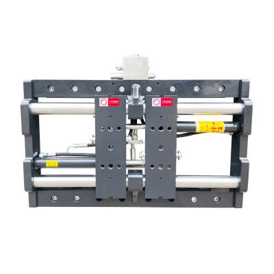
Fork positioners can easily handle pallets with different widths to help meet complex material handling demands. The M series fork positioner allows you to hydraulically move the forks closer together or further apart, individually or together.
This is particularly useful when you have to handle a variety of pallet sizes. Damage to pallets and products will be reduced as well.
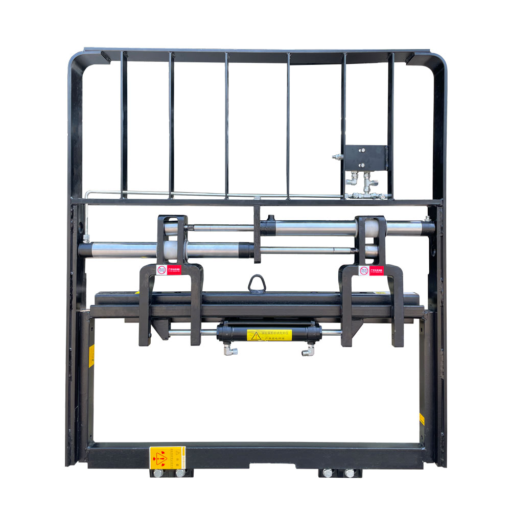
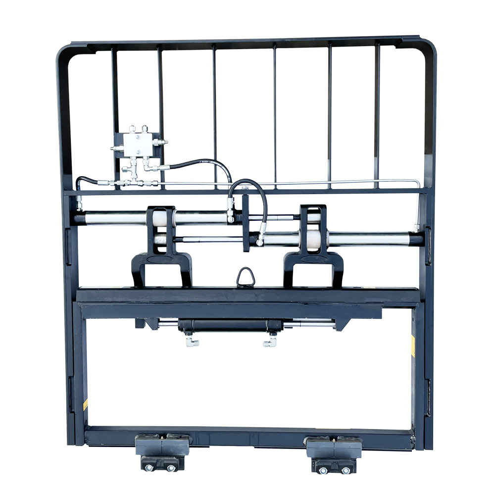
Important parts configuration:
Hydraulic system: The use of multi-functional combined control valve, with 24° cone seal, greatly improves the reliability of the hydraulic system.
Structural parts: The shift fork is made of integral alloy steel castings, with beautiful appearance and reliable performance.
Mechanical performance: The use of control valves to ensure that the two forks can run synchronously, the forks are controlled by double cylinders, and the stability is good;
the standard forks of the forklift are used, which has good versatility and easy installation.
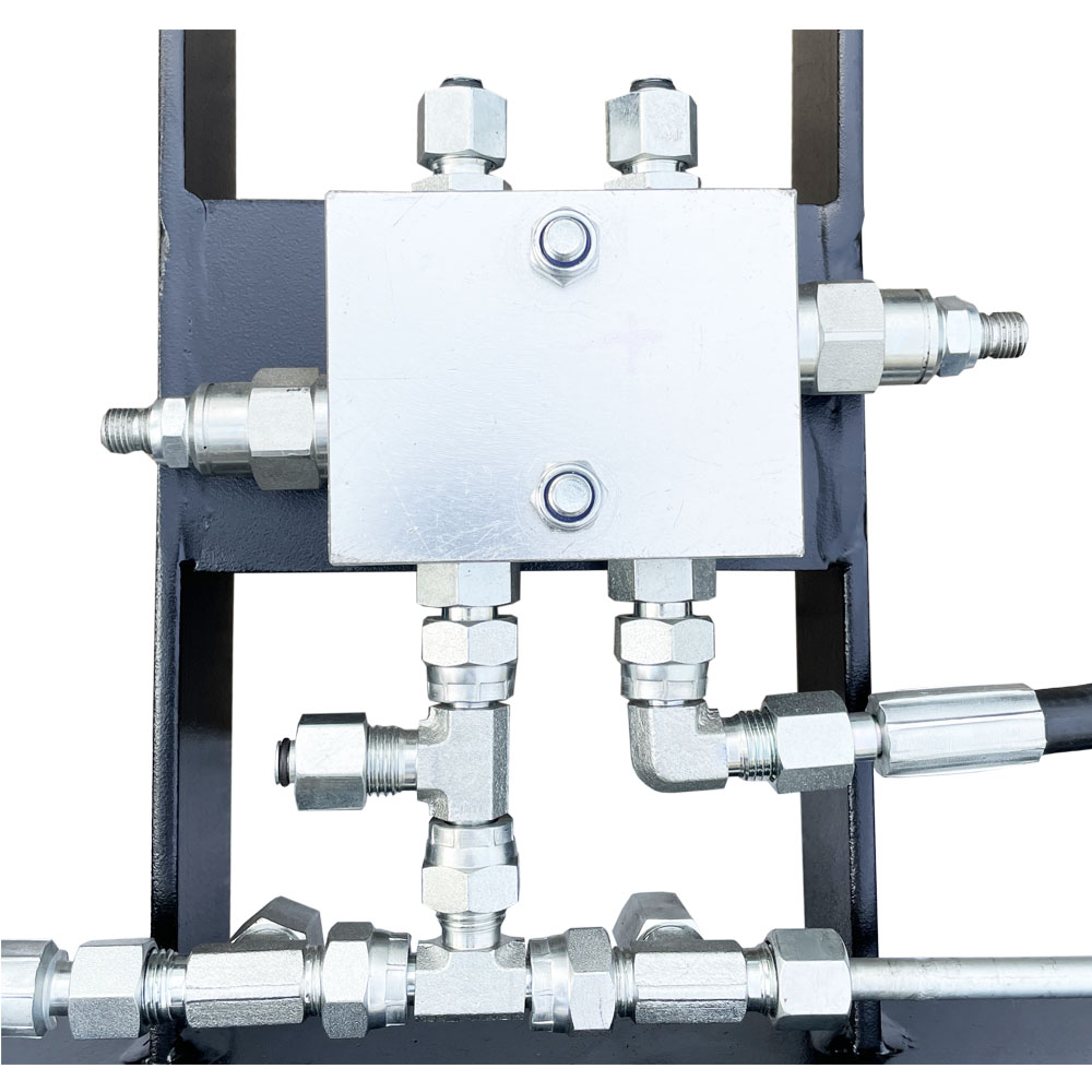
Side shift function is optional, the specific configuration is:
Only fork positioner,no side shift,2 sets of additional oil circuits are required (no control valve);
Fork positioner and side shift,2 sets of additional oil circuits are required (with control valve);
Only fork positioner,no side shift,1 set of additional oil circuits are required(with control valve);
Note:
1. Please obtain the actual comprehensive load capacity of the forklift/attachment from the forklift manufacturer.
2. Fork pitch range: the minimum value is the inner distance of the two forks when the forks are closed, the maximum value is the outer distance of the two forks when the forks are opened.
3. Non-standard sizes not included in the form need to be booked separately.
Model
Pressure(Bar)
Flow(L/min)
Max.
Min.
Rec.
Max.
M**G
180
11
15
19
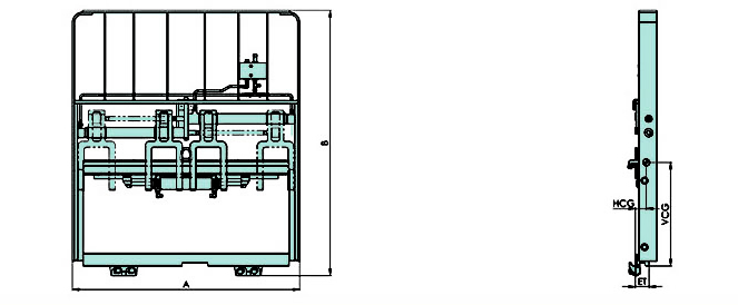
Capacity@
Load Center
Mounting
Class
Opening
Range
Total
Side Shift
Fork pocket
width
Min. Truck
Carrier Width
Overall
Width
Overall
Height
Effective
Thickness
Horizontal of
Gravity Centre
Avaliable
Forklift
Model
Weight
M18G-A1
1800@500
2
100-900
±100
100
895
1018
1245
139
62
50
1-1.8T
M25G-A1
2500@500
2
100-970
±100
100
940
1088
1245
152
62
50
2-2.5T
M30G-A1
3000@500
3
100-1025
±100
125
970
1148
1336
182
68
50
3-3.5T
M45G-A1
4500@500
3
100-1300
±100
150
1180
1428
1345
260
70
50
4-4.5T





 IPv6 network supported